
阅读量:1
在核心堆叠基础上增加服务器区交换机配置
配置服务器区交换机 SW1与SW2堆叠组成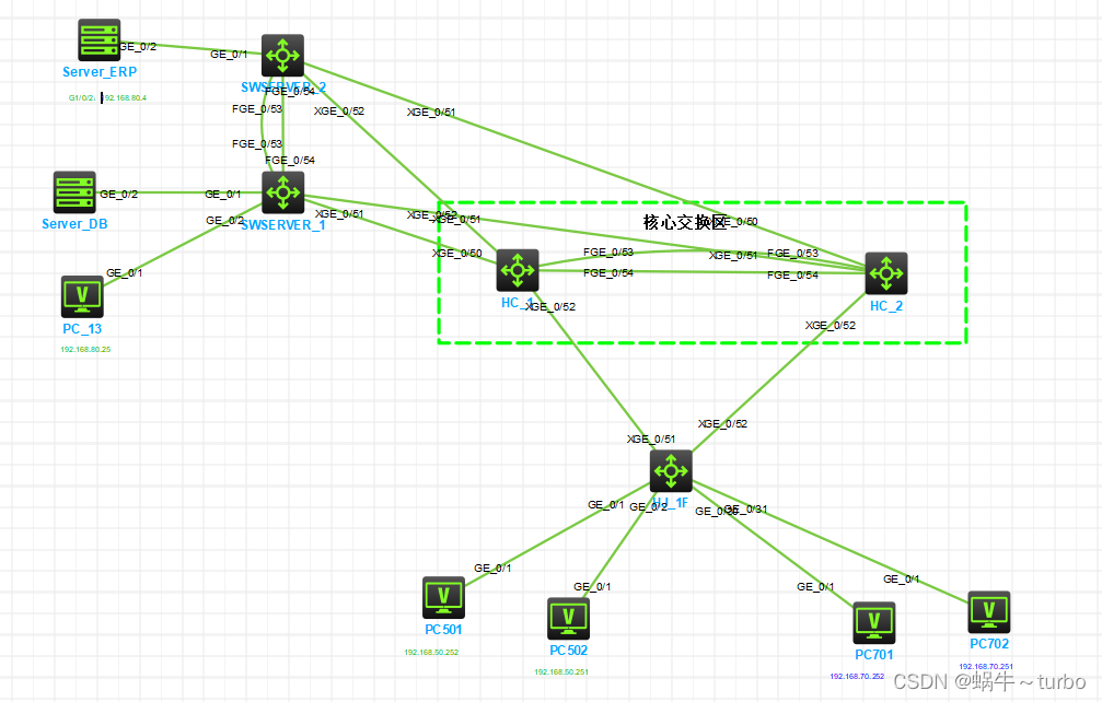
HCL SERVER2 的配置界面如下图: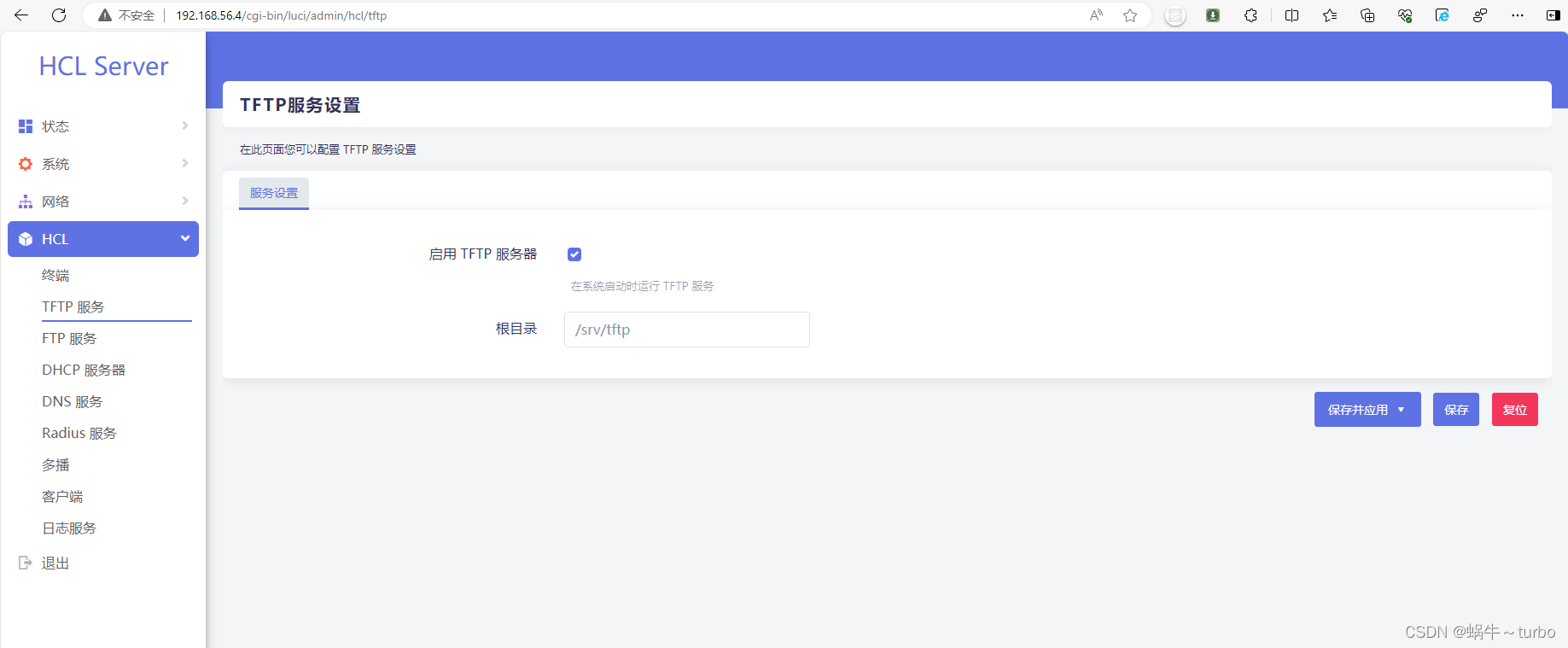
[H3C]sys SWSERVER_1
[SWSERVER_1]irf domain 1 //设置堆叠域编号为1 因为同一个网络中已存在一个堆叠了,同网络的堆叠域编号可以相同,但是不建议
[SWSERVER_1]dis irf
MemberID Role Priority CPU-Mac Description
*+1 Master 32 8a86-c99e-0404 —
- indicates the device is the master.
- indicates the device through which the user logs in.
The bridge MAC of the IRF is: 8a86-c99e-0400
Auto upgrade : yes
Mac persistent : 6 min
Domain ID : 1
[SWSERVER_1]irf member 1 priority 32 //设置设备IRF优先级
[SWSERVER_1]interface range fge1/0/53 to fge1/0/54 //选择端口范围fge1/0/53 to fge1/0/54
[SWSERVER_1-if-range]shut
[SWSERVER_1-if-range]shutdown //关闭物理端口 fge1/0/53 to fge1/0/54
[SWSERVER_1-if-range]qu
[SWSERVER_1]irf-port 1/2
[SWSERVER_1-irf-port1/2]port group interface fge1/0/53 //将40G fge1/0/53接口添加到IRF端口组中
//系统会提示,为了成功设置IRF,您必须执行以下任务:完成IRF配置后保存配置。执行“IRF -port-configuration active”命令激活IRF端口。
You must perform the following tasks for a successful IRF setup:
Save the configuration after completing IRF configuration.
Execute the “irf-port-configuration active” command to activate the IRF ports.
[SWSERVER_1-irf-port1/2]port group interface fge1/0/54 //将40G fge1/0/53接口添加到IRF端口组中
[SWSERVER_1-irf-port1/2]interface range fge1/0/53 to fge1/0/54 //选择端口范围fge1/0/53 to fge1/0/54
[SWSERVER_1-if-range]undo shutdown //开启物理端口
[SWSERVER_1-if-range]qu
[SWSERVER_1]save f //保存配置
[SWSERVER_1]irf-port-configuration active
[H3C]sysname SWERVER_2
[SWERVER_2]irf member 1 renumber 2 //设置设备编号为2 改完后需要重启才能生效
Renumbering the member ID may result in configuration change or loss. Continue?[Y/N]:Y
Please reboot the device for the new member ID to take effect.
[SWERVER_2]qu
<SWERVER_2>rebooot
同样需要先设置irf域编码
[SWERVER_2]irf domain 1
[SWERVER_2]irf-port 2/1 //绑定irf端口配置 注意交叉顺序
[SWERVER_2-irf-port2/1]
再按SW1的方式将SW2交换机的 40G的53、54号(此时端口号机器编号为2,fge2/0/53 to fge2/0/54)端口加入到IRF-Port中
激活irf后连接通过53、54号端口连接设备,
此时如果配置都正确且生效的话,两台交换机分自动重启,如果没有重启,先将连线拆下,再检查两台交换机用于堆叠的物理端口是否开启,如果为shutdown,在启用后,并重新激活一下irf配置。再连接线缆。
[SWSERVER_1]interface fge1/0/53
[SWSERVER_1-FortyGigE1/0/53]dis th
interface FortyGigE1/0/53
shutdown
irf 配置完成后 配置SWSERVER vlan
<SWSERVER_1>sys
[SWSERVER_1]vlan 50 60 70 80
[SWSERVER_1]dis vlan
Total VLANs: 5
The VLANs include:
1(default), 50, 60, 70, 80
创建二层链路聚合口 BAGG1
[SWSERVER_1]interface Bridge-Aggregation 1
[SWSERVER_1]qu
[SWSERVER_1]interface range xge1/0/51 xge1/0/52 xge2/0/51 xge2/0/52
[SWSERVER_1-if-range]port link-aggregation group 1
[SWSERVER_1-if-range]qu
//配置BAGG1允许通过VLNA
[SWSERVER_1]interface Bridge-Aggregation 1
[SWSERVER_1-Bridge-Aggregation1]port link-type trunk
[SWSERVER_1-Bridge-Aggregation1]port trunk permit vlan 50 60 70 80
返回核心交换机sys
[SWHC1]vlan 80 //创建VLNA80
[SWHC1]int vlan 80
[SWHC1-Vlan-interface80]ip address 192.168.80.253 24
[SWHC1-Vlan-interface80]qu
//创建二层链路聚合口 2
[SWHC1]interface Bridge-Aggregation 2
[SWHC1-Bridge-Aggregation2]qu
[SWHC1]interface range xge1/0/50 xge1/0/51 xge2/0/50 xge2/0/51
[SWHC1-if-range]port link-aggregation group 2
[SWHC1-if-range]qu
[SWHC1]interface Bridge-Aggregation 2
[SWHC1-Bridge-Aggregation2]port link-type trunk
[SWHC1-Bridge-Aggregation2]port trunk permit vlan 50 60 70 80
[SWHC1-Bridge-Aggregation2]qu
[SWHC1]save f
配置完成后 依次将对应的线连接上如图所示。
完成验证如图: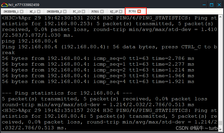
[SWHC1]acl number 3080 //创建ACL 3080 指定允许通过的服务
[SWHC1-acl-ipv4-adv-3080]
[SWHC1-acl-ipv4-adv-3080] rule 15 permit tcp destination 192.168.80.4 0 destination-port eq www
[SWHC1-acl-ipv4-adv-3080]rule 21 permit tcp destination 192.168.80.4 0 destination-port eq ftp
[SWHC1-acl-ipv4-adv-3080]rule 30 permit tcp destination 192.168.80.4 0 destination-port eq dns
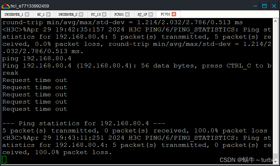
[SWHC1-acl-ipv4-adv-3080]rule 900 deny tcp destination 192.168.80.4 0
[SWHC1-acl-ipv4-adv-3080]rule 999 deny icmp destination 192.168.80.4 0
[SWHC1-acl-ipv4-adv-3080]int vlan 70 //进入VLNA 70
[SWHC1-Vlan-interface70] packet-filter 3080 inbound //将ACL 3080 应用到VLNA 70 的进入口
[SWHC1-Vlan-interface70]qu
[SWHC1-Vlan-interface70]save f
从PC701 再ping 192.168.80.4 如下图
telnet 192.168.80.4 21 如下图 是可以访问的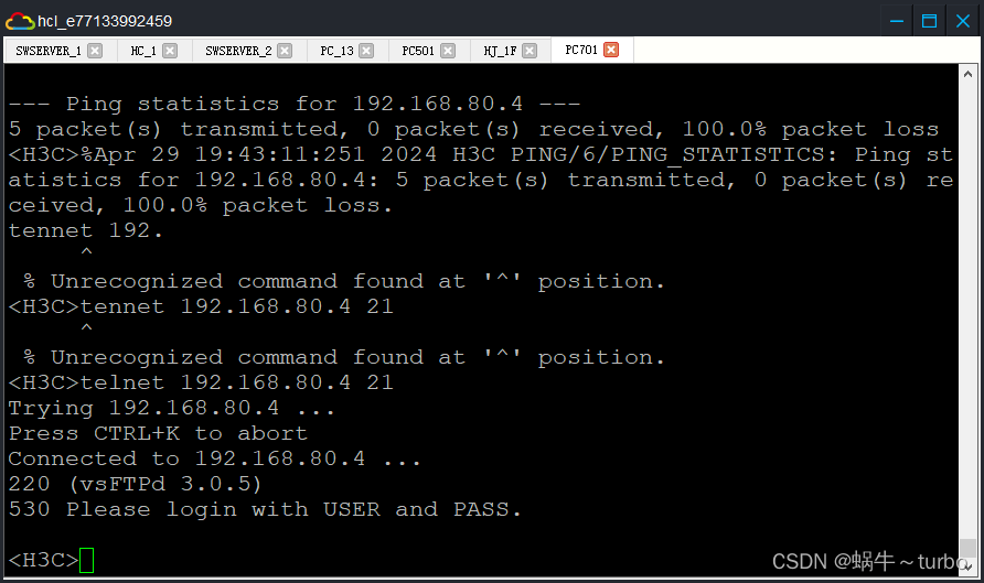
22号端口服务 是不允许的。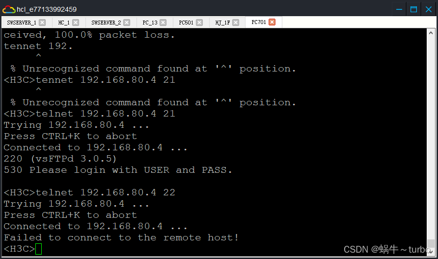
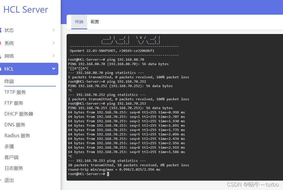
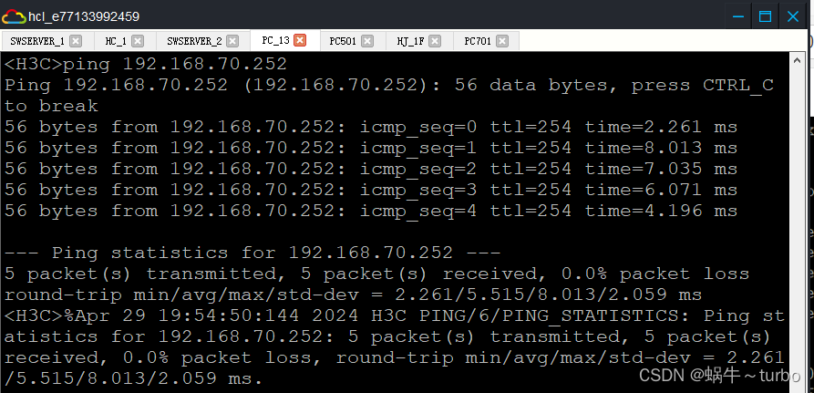
SERVER_1管理页面终端 root 123456 可以ping通 192.168.70.253 但ping 不通 192.168.70.252& 50.252 暂不知道原因,有知道的朋友欢迎留言。
